Category Archives: Imaging

CT Contrast Administration Via Intraosseous Cathether

The standard of care in vascular access in trauma patients is the intravenous route. Unfortunately, not all patients have veins that can be quickly accessed by prehospital providers. Introduction of the intraosseous device (IO) has made vascular access in the field much more achievable. And it appears that most fluids and medications can be administered via this route. But what about iodinated contrast agents via IO for CT scanning?

Physicians at Henry Ford Hospital in Detroit published a case report on the use of this route for contrast administration. They treated a pedestrian struck by a car with a lack of IV access sites by IO insertion in the proximal humerus, which took about 30 seconds. They then intubated using rapid sequence induction, with drugs injected through the IO device. They performed full CT scanning using contrast injected through the site using a power injector. Images were excellent, and ultimately the patient received an internal jugular catheter using ultrasound. The IO line was then discontinued.

This paper suggests that the IO line can be used as access for injection of CT contrast if no IV sites are available. Although it is a single human case, a fair amount of studies have been done on animals (goats?). The animal studies show that power injection works adequately with excellent flow rates.

The authors prefer using an IO placement site in the proximal humerus. This does seem to cause a bit more pain, and takes a little practice see the video above). A small xylocaine flush can be administered to reduce injection discomfort in awake patients. Additionally, the arm cannot be raised over the head for the torso portion of the scan.

Bottom line: CT contrast can be injected into an intraosseous line (IO) with excellent imaging results. Insert the IO in a site that you are comfortable with. I do not recommend power injection at this time. Although the marrow cavity can support it, the connecting tubing may not. Have your radiologist hand-inject and time the scan accordingly.

Note: long term effects of iodinated contrast in the bone marrow are not known. For this reason, and because of smaller marrow cavities, this technique is not suitable for pediatric patients.

Related post: Air embolism from an intraosseous line

Reference: Intraosseous injection of iodinated computed tomography contrast agent in an adult blunt trauma patient. Annals Emerg Med 57(4):382-386, 2011.

Print Friendly, PDF & Email

CT Scan Images Simplified

Ever wonder what is going on when you drag your mouse across a CT image, or when you change the “window” settings of an image from lung to abdomen? It all has to do with the way CT generated xray information is displayed, and how your eyes and brain perceive it.

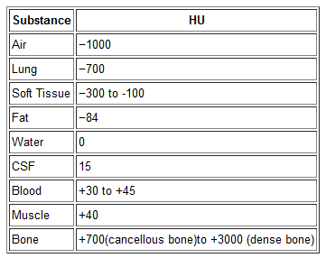
Let’s get down to basics. The first thing needed is to understand the concept of radiodensity. The CT scanner uses a set of software algorithms to determine the amount of x-radiation absorbed by every element in a plane of tissue. Each of these elements is represented by a pixel on the video display, and the density (amount of x-radiation absorbed) is measured in Hounsfield units. This scale was developed by Sir Godfrey Hounsfield, who set the radiodensity of water at 0, and air at -1000. The scale extends in the positive direction to about +4000, which represents very dense metals. See the table for the density of common substances on CT.

When you view a CT scan on a video display, two important numbers are displayed on screen. The first is the window width (W), which describes the range of Hounsfield units displayed. The maximum window width possible is usually about 2000, but our eyes are not capable of seeing this many shades. Actually, we can really only distinguish about 16 shades of gray. So the window width is divided by 16, and each group of Hounsfield values is converted to one of 16 shades of gray. The lowest Hounsfield numbers in the window range are shown as black, and the highest are white.

The second important number is the window level (L). This is the Hounsfield number in the center of the window width. So let’s look at some typical examples of W/L settings.

The abdomen contains mostly soft tissue, which is just a little denser than water. So most of the abdominal contents have Hounsfield values from 0 to 100 or so. A typical abdominal scan W/L setting is 350/50. This means that a total range of 350 different densities are displayed, centered on a density of 50 Hounsfield units ( range is -125 to 225 HU). Each difference of 22 HU will show up as a different shade of gray. So this narrow window allows us to distinguish relatively subtle differences in density.

The chest cavities are primarily air-filled, and the lungs are very low density. So it makes sense that a typical lung W/L setting is 1500/-500. The window ranges from -1250 to +250 HU, and a wider range of 94 HU represents one shade of gray. This is typical of body regions with a wider range of densities.

Finally, bone windows are usually 2000/250. This window is centered above the usual tissue densities, and is very wide so that it shows a wide range of densities in only 16 shades of gray. Thus, the contrast appears very low.

On most displays, the window width increases as you drag the mouse to the right. This increases the range of densities in a shade of gray, thus decreasing the overall amount of contrast in the image. Dragging the mouse down decreases the window level, moving it toward the air end of the spectrum. This allows you to center your window on the type of tissue you are interested in viewing and adjust your ability to distinguish objects with a lot or only a little contrast (see table above).

I apologize to my radiology colleagues in advance for this simplistic explanation. Trauma professionals have minimal exposure (pun intended) to the physics and details of radiographic imaging. We are much more interested in effectively using this technology to save our patients’ lives.

Print Friendly, PDF & Email

Arms Up or Arms Down In Torso CT Scans?

CT scan is a valuable tool for initial screening and diagnosis of trauma patients. However, more attention is being paid to radiation exposure and dosing. Besides selecting patients carefully and striving for ALARA radiation dosing (as low as reasonably achievable) by adjusting technique, what else can be done? Obviously, shielding parts of the body that do not need imaging is simple and effective. But what about simply changing body position?

One simple item to consider is arm positioning in torso scanning. There are no consistent recommendations for use in trauma scanning. Patients with arm and shoulder injuries generally keep the affected upper extremity at their side. Radiologists prefer to have the arms up if possible to reduce scatter and provide clearer imaging.

A recently published article looked at arm positioning and its effect on radiation dose. A retrospective review of 690 patients used dose information computed by the CT software and displayed on the console. Radiation exposure was estimated using this data and was stratified by arm positioning. Even though there are some issues with study design, the results were impressive.

The dose results were as follows:

  • Both arms up: 19.2 mSv (p<0.0000001)
  • Left arm up: 22.5 mSv
  • Right arm up: 23.5 mSv
  • Arms down: 24.7 mSv

Bottom line: Do everything you can to reduce radiation exposure:

  1. Be selective with your imaging. Do you really need it?
  2. Work with your radiologists and physicists to use techniques that reduce dose yet retain image quality
  3. Shield everything that’s not being imaged.
  4. Think hard about getting CT scans in children
  5. Raise both arms up during torso scanning unless injuries preclude it.

Reference: Influence of arm positioning on radiation dose for whole body computed tomography in trauma patients. J Trauma 70(4):900-905, 2011.

Print Friendly, PDF & Email